Control Interface Specification and Robot Limits
Overview
Realtime control commands sent to the robot must satisfy a set of recommended and necessary conditions. Recommended conditions ensure optimal and stable behavior, while necessary conditions are strict safety and feasibility requirements. Violating any necessary condition results in an immediate motion abort.
The executed robot trajectory is based on the user-defined trajectory but adjusted to ensure that recommended conditions are respected. As long as all necessary conditions are satisfied, the robot will follow the commanded trajectory; however, it will only match it exactly if the recommended conditions are also fulfilled.
If a necessary condition is violated, the system raises an error and stops the
motion. For example, if the first point of a user-provided joint trajectory differs
too much from the robot’s actual start configuration
(\(q(t=0) \neq q_c(t=0)\)), a start_pose_invalid error is triggered.
All constants referenced in the equations below are provided in the Limits for Franka Emika Robot (FER) and Limits for Franka Research 3 (FR3) sections.
Control Modes
Joint Space Control Requirements
Necessary Conditions
\(q_{min} < q_c < q_{max}\)
\(-\dot{q}_{max} < \dot{q}_c < \dot{q}_{max}\)
\(-\ddot{q}_{max} < \ddot{q}_c < \ddot{q}_{max}\)
\(-\dddot{q}_{max} < \dddot{q}_c < \dddot{q}_{max}\)
Recommended Conditions
\(-{\tau_j}_{max} < {\tau_j}_d < {\tau_j}_{max}\)
\(-\dot{\tau_j}_{max} < \dot{\tau_j}_d < \dot{\tau_j}_{max}\)
Initial trajectory requirements:
\(q = q_c\)
\(\dot{q}_c = 0\)
\(\ddot{q}_c = 0\)
Final trajectory requirements:
\(\dot{q}_c = 0\)
\(\ddot{q}_c = 0\)
Torque Control Requirements
Necessary Conditions
\(-\dot{\tau_j}_{max} < \dot{{\tau_j}_d} < \dot{\tau_j}_{max}\)
Recommended Conditions
\(-{\tau_j}_{max} < {\tau_j}_d < {\tau_j}_{max}\)
Initial controller requirements:
\({\tau_j}_d = 0\)
Cartesian Space Control Requirements
Necessary Conditions
\(T\) is a proper transformation matrix.
\(-\dot{p}_{max} < \dot{p}_c < \dot{p}_{max}\) (Cartesian velocity)
\(-\ddot{p}_{max} < \ddot{p}_c < \ddot{p}_{max}\) (Cartesian acceleration)
\(-\dddot{p}_{max} < \dddot{p}_c < \dddot{p}_{max}\) (Cartesian jerk)
Conditions derived from inverse kinematics:
\(q_{min} < q_c < q_{max}\)
\(-\dot{q}_{max} < \dot{q}_c < \dot{q}_{max}\)
\(-\ddot{q}_{max} < \ddot{q}_c < \ddot{q}_{max}\)
Recommended Conditions
Conditions derived from inverse kinematics:
\(-{\tau_j}_{max} < {\tau_j}_d < {\tau_j}_{max}\)
\(-\dot{\tau_j}_{max} < \dot{{\tau_j}_d} < \dot{\tau_j}_{max}\)
Initial trajectory requirements:
\({}^OT_{EE} = {{}^OT_{EE}}_c\)
\(\dot{p}_c = 0\)
\(\ddot{p}_c = 0\)
Final trajectory requirements:
\(\dot{p}_c = 0\)
\(\ddot{p}_c = 0\)
System Limits for Supported Robot Models
Limits for Franka Research 3 (FR3)
Cartesian-space limits:
Name |
Translation |
Rotation |
Elbow |
|---|---|---|---|
\(\dot{p}_{max}\) |
3.0 \(\frac{\text{m}}{\text{s}}\) |
2.5 \(\frac{\text{rad}}{\text{s}}\) |
2.620 \(\frac{rad}{\text{s}}\) |
\(\ddot{p}_{max}\) |
9.0 \(\frac{\text{m}}{\text{s}^2}\) |
17.0 \(\frac{\text{rad}}{\text{s}^2}\) |
10.0 \(\frac{rad}{\text{s}^2}\) |
\(\dddot{p}_{max}\) |
4500.0 \(\frac{\text{m}}{\text{s}^3}\) |
8500.0 \(\frac{\text{rad}}{\text{s}^3}\) |
5000.0 \(\frac{rad}{\text{s}^3}\) |
Joint-space limits:
Name |
Joint 1 |
Joint 2 |
Joint 3 |
Joint 4 |
Joint 5 |
Joint 6 |
Joint 7 |
Unit |
|---|---|---|---|---|---|---|---|---|
\(q_{max}\) |
2.9007 |
1.8361 |
2.9007 |
-0.1169 |
2.8763 |
4.6216 |
3.0508 |
\(\text{rad}\) |
\(q_{min}\) |
-2.9007 |
-1.8361 |
-2.9007 |
-3.0770 |
-2.8763 |
0.4398 |
-3.0508 |
\(\text{rad}\) |
\(\dot{q}_{max}\) |
2.62 |
2.62 |
2.62 |
2.62 |
5.26 |
4.18 |
5.26 |
\(\frac{\text{rad}}{\text{s}}\) |
\(\ddot{q}_{max}\) |
10 |
10 |
10 |
10 |
10 |
10 |
10 |
\(\frac{\text{rad}}{\text{s}^2}\) |
\(\dddot{q}_{max}\) |
5000 |
5000 |
5000 |
5000 |
5000 |
5000 |
5000 |
\(\frac{\text{rad}}{\text{s}^3}\) |
\({\tau_j}_{max}\) |
87 |
87 |
87 |
87 |
12 |
12 |
12 |
\(\text{Nm}\) |
\(\dot{\tau_j}_{max}\) |
1000 |
1000 |
1000 |
1000 |
1000 |
1000 |
1000 |
\(\frac{\text{Nm}}{\text{s}}\) |
\(\dot{q}_{offset}\) |
0.6599 |
0.2517 |
0.2000 |
0.3533 |
0.5757 |
0.4878 |
0.4628 |
\(\frac{\text{rad}}{\text{s}}\) |
\(\ddot{q}_{dec}\) |
6.0 |
2.585 |
3.5 |
4.0 |
17.0 |
5.5 |
17.0 |
\(\frac{\text{rad}}{\text{s}^2}\) |
The arm reaches its maximum extension when joint 4 is at \(q_{elbow-flip} = -0.467002423653011\:rad\).
Position-Based Velocity Limits
Important
The maximum joint velocity depends on both the joint position and the direction of motion. The position-dependent velocity limits can be queried via:
Robot::getUpperJointVelocityLimits(
    const std::array<double, 7UL>& joint_positions
);
Robot::getLowerJointVelocityLimits(
    const std::array<double, 7UL>& joint_positions
);
Position-based limits are computed as:
These limits ensure safety and may be more restrictive than the nominal hardware capabilities.
Users may choose their own joint ranges and velocity limits depending on the requirements of their motion generator.

Position-based velocity limits.
Suggested rectangular position–velocity limits:
Name |
Joint 1 |
Joint 2 |
Joint 3 |
Joint 4 |
Joint 5 |
Joint 6 |
Joint 7 |
Unit |
|---|---|---|---|---|---|---|---|---|
\(q_{max}\) |
2.3476 |
1.5454 |
2.4937 |
-0.4226 |
2.5100 |
4.2841 |
2.7045 |
\(\text{rad}\) |
\(q_{min}\) |
-2.3476 |
-1.5454 |
-2.4937 |
-2.7714 |
-2.5100 |
0.7773 |
-2.7045 |
\(\text{rad}\) |
\(\dot{q}_{max}\) |
2 |
1 |
1.5 |
1.25 |
3 |
1.5 |
3 |
\(\frac{\text{rad}}{\text{s}}\) |
Limits for Franka Emika Robot (FER)
Cartesian-space limits:
Name |
Translation |
Rotation |
Elbow |
|---|---|---|---|
\(\dot{p}_{max}\) |
1.7 \(\frac{\text{m}}{\text{s}}\) |
2.5 \(\frac{\text{rad}}{\text{s}}\) |
2.1750 \(\frac{rad}{\text{s}}\) |
\(\ddot{p}_{max}\) |
13.0 \(\frac{\text{m}}{\text{s}^2}\) |
25.0 \(\frac{\text{rad}}{\text{s}^2}\) |
10.0 \(\frac{rad}{\text{s}^2}\) |
\(\dddot{p}_{max}\) |
6500.0 \(\frac{\text{m}}{\text{s}^3}\) |
12500.0 \(\frac{\text{rad}}{\text{s}^3}\) |
5000.0 \(\frac{rad}{\text{s}^3}\) |
Joint-space limits:
Name |
Joint 1 |
Joint 2 |
Joint 3 |
Joint 4 |
Joint 5 |
Joint 6 |
Joint 7 |
Unit |
|---|---|---|---|---|---|---|---|---|
\(q_{max}\) |
2.8973 |
1.7628 |
2.8973 |
-0.0698 |
2.8973 |
3.7525 |
2.8973 |
\(\text{rad}\) |
\(q_{min}\) |
-2.8973 |
-1.7628 |
-2.8973 |
-3.0718 |
-2.8973 |
-0.0175 |
-2.8973 |
\(\text{rad}\) |
\(\dot{q}_{max}\) |
2.1750 |
2.1750 |
2.1750 |
2.1750 |
2.6100 |
2.6100 |
2.6100 |
\(\frac{\text{rad}}{\text{s}}\) |
\(\ddot{q}_{max}\) |
15 |
7.5 |
10 |
12.5 |
15 |
20 |
20 |
\(\frac{\text{rad}}{\text{s}^2}\) |
\(\dddot{q}_{max}\) |
7500 |
3750 |
5000 |
6250 |
7500 |
10000 |
10000 |
\(\frac{\text{rad}}{\text{s}^3}\) |
\({\tau_j}_{max}\) |
87 |
87 |
87 |
87 |
12 |
12 |
12 |
\(\text{Nm}\) |
\(\dot{\tau_j}_{max}\) |
1000 |
1000 |
1000 |
1000 |
1000 |
1000 |
1000 |
\(\frac{\text{Nm}}{\text{s}}\) |
The arm reaches its maximum extension when joint 4 is at \(q_{elbow-flip} = -0.467002423653011\:rad\). This parameter determines the elbow flip direction.
Kinematic Configuration
Denavit–Hartenberg Parameters
The Denavit–Hartenberg parameters for the Franka Research 3 kinematic chain (following Craig’s convention) are shown below:
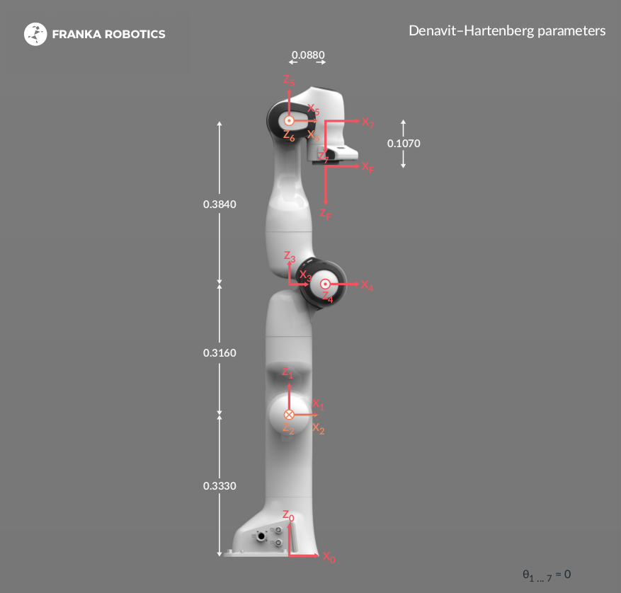
Franka Research 3 kinematic chain.
Joint |
\(a\;(\text{m})\) |
\(d\;(\text{m})\) |
\(\alpha\;(\text{rad})\) |
\(\theta\;(\text{rad})\) |
|---|---|---|---|---|
Joint 1 |
0 |
0.333 |
0 |
\(\theta_1\) |
Joint 2 |
0 |
0 |
\(-\frac{\pi}{2}\) |
\(\theta_2\) |
Joint 3 |
0 |
0.316 |
\(\frac{\pi}{2}\) |
\(\theta_3\) |
Joint 4 |
0.0825 |
0 |
\(\frac{\pi}{2}\) |
\(\theta_4\) |
Joint 5 |
-0.0825 |
0.384 |
\(-\frac{\pi}{2}\) |
\(\theta_5\) |
Joint 6 |
0 |
0 |
\(\frac{\pi}{2}\) |
\(\theta_6\) |
Joint 7 |
0.088 |
0 |
\(\frac{\pi}{2}\) |
\(\theta_7\) |
Flange |
0 |
0.107 |
0 |
0 |
Note
\({}^0T_{1}\) describes the pose of frame 1 in frame 0.
The full kinematic chain is computed as:
\({}^0T_{2} = {}^0T_{1} \cdot {}^1T_{2} \cdot {}^2T_{n}\)